Cast-in-situ pile
 Simplex pile
 Franki pile
 Vibro pile
 Vibro Expanded Pile
  Raymond Pile
 Mac Arthur pedestal Pile
 Boring Grab Cutting Teeth for Rotary Drilling

Cast in situ Piles
Installation Process:


Cast-in-situ piles are those piles which are cast in position inside the ground. it is As it is casted in situation. So it is called cast-in-situ pile
· Most common pile in Bangladesh recent years
· first used in 1952 but mainly in the period 1962 to 1981
· Not necessary to reinforce the pile in ordinary cases or in places where the pile is completely submerged in the soil.
· It is created and used in the desired position
Types of Cast-in-situ pile:
1. Simplex pile:
This type of pile may be driven through soft or hard soil. A steel tube having an internal dia of the pile and 20mm in thickness is driven into the ground. To facilitate driving of the pile, the steel tube is fitted with a detachable steel shoe that completely closes the bottom of the tube

The metallic shoe remains in place and hence a new one is needed for each pile. In case the pile is required to be reinforced ,the reinforcement cage is lowered into the steel tube prior to the pouring of concrete.
2. Franki Pile
This type of pile has an enlarged base and a corrugated stem. A steel tube, having its internal diameter equal to the diameter of the pile required, is held vertical at the ground level with the help of leads. A charge of concrete is poured at its base filling the bottom 60 cm to 90 cm of the tube. The charge of concrete is consolidated into a solid plug by the blows of the drop hammer on the plug pull the tube down on account of the friction developed between the concrete and the inside surface of the tube.
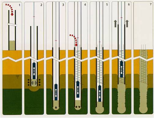
When the tube has been driven to the required depth, it is slightly raised and the plug is forced out of the tube by hammering. The reinforcement cage (if needed) is then lowered inside the tube. A fresh charge of concrete is then poured in the tube and rammed well by the drop hammer while the tube is pulled up a short distance. The repeated process produces a series of corrugations on the stem of the pile and the pile is thus complicated.
3. Vibro Pile:
This type of pile is best suited for places where the ground is soft and others little frictional resistance to the flow of concrete. A steel tube filled with a cast iron shoe is first driven to the required depth. There is a water-tight joint between the shoe and the casting so that even if the pile is to driven in water-logged ground, the soil and the sub-soil water cannot find an access in the tube before the concreting is done. The reinforcement cage (if needed) is lowered in the

tube at this stage. The charge of concrete is then poured in the tube. The extraction of the tube and ramming of concrete is effected by the upward and the downward blows of the hammer. The tube is connected to the hammer by extracting links. During the upward blow of the hammer, the tube is raised up by a short distance and the concrete moves down to fill the space left by the tube. During the downward blow, the concrete is compacted and rammed outwards thereby forming corrugated surface for pile. This results in increased friction between the pile surface and the surrounding ground.
3. Vibro Expanded Pile
In situation where it is desired to have increased frictional resistance between the pile stem and the surrounding ground, the surface of a vibro-pile is expanded generally to achieve the object. This increases the bearing resistance of a vibro pile. In this process, a sheet tube of the required diameter of the pile having a detachable cast iron conical shoe at its base, is driven to the required depth. A charge of concrete (filling a good length of tube) is poured and the tube is completely withdrawn leaving the cast iron shoe and the charge of concrete down in the pile hole.

The withdrawn tube is fitted with a special flat iron shoe and once again driven in the same hole. The charge of concrete down below gets expanded to nearly double its area by the process. If required, another charge of concrete is poured and the process repeated. The reinforcement cage is thereafter lowered in the tube (if needed) and the pile is complicated as usual.
4. Raymond Pile
This type of pile is constructed in lengths varying from 6 to 12 m. the diameter of the pile varies from 40 to 60 cm at top and the diameter at its base is slightly smaller, varying from 20 to 28 cm so as to uniform taper to pile. The thickness of the outer shell depends upon the pile diameter and site conditions. The thin steel shell is reinforced with hard drawn wire spiral spaced at 8 cm centre to centre. This shell is closed at the bottom with a steel boot.

The shell is placed over a collapsible mandrel having the same taper as the pile and both are driven to the desired depth. The mandrel is then withdrawn leaving the shell in the ground. The shell is gradually filled with concrete up to the top. This forms a Raymond pile. The function of shell outside the concrete core is to prevent the adjoining soil and the sub-soil water coming in contact with fresh concrete.
5. Mac Arthur pedestal Pile
In this type of pile the apparatus consists of an outer casting (a hollow steel pipe) and an inner core. The bottom of the core is of a size that it completely closes the open base of the casting when inserted inside. The core and the casting are together driven into the ground to the required depth. The core is removed and a charge of concrete is poured in the casting. The core is replaced in the casting, so that it is in contact with the concrete. The casting is then pulled up a short distance of 60 cm to 90 cm and on account of the pressure of the core and the hammer, the concrete is rammed out. Again the core is removed, another charge of concrete poured and the operation repeated.

When the bulb at the base has been formed to the required area, the casting is gradually withdrawn after filling with concrete so as to form a stem of constant diameter. If desired, the pile can also be reinforced
Bored cast in situ Piles Installation Process:
a) Loosening Of Soil
1. Cutting and Scraping:

- Ripping
- Percussion
b) Removal Of soil
(i) Intermittent Transport
¨ Rope Grab
¨ Rotary Drill
(ii) Continuous Transport
v Flush Drilling
v Continuous Auger
c) Temporary Support
I. Drill Casing
Ø Vibrating
Ø Oscillating
Ø Rotating
II. Drilling Mud
o Water
o Bentonite
o Polymer
d) Enlarged Base
ü Under reaming
ü Grouting
ü Plug Expulsion
e) Casting Of Pile:

Cast in situ Piles
Installation Process:

Centering and Placing auger:


Start Boring:

Placing of drilling case:
Casting Of Pile

 |
Placing of reinforcement case
—
|
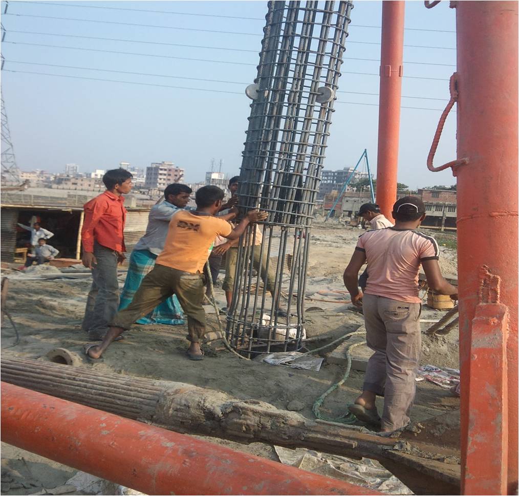
Lapping of two reinforcement case

Pouring concrete with tremie pipe and started casting

Concrete are getting compacted by ups and down of tremie pipe
Comparison between Theory and Practical Field
Theoretically
|
Practical Field
|
§ Pouring of Concrete and Withdrawing of steel tube gradually
|
Steel tube is withdrawn after 28 days
|
§ Polymer, Bentonite, or Steel Case is used
|
Only Bentonite solution is used
|
§ Auger or rotary drill is used
|
Only Rotary drill is used
|
Some practical problem and its solution
Problem
|
Solution
|
§ Rocky layer of soil with stone
|
Abort drilling
|
§ Rising water from the bottom of hole
|
Pump the water. Best, use precast pile
|
§ Corrosion can be occurred
|
Soil test is needed. Corrosion resistant cement
|
Advantages of Cast in Situ Pile
§ Length can be readily varied
§ End enlargement
§ Material of pile is not dependent
§ Long length installation
§ Little or no noise or vibration
§ Designing Accuracy
Disadvantages of Cast in Situ Pile
§ Cannot be used under water
§ Displacement of reinforced
§ Dumping of concrete from a great height
§ Inspection is not possible; voids may be left
§ Contact of water of concrete to the dry soil if uncased
§ Freshly laid concrete is susceptible to soil components
§ Driving of adjacent piles may rupture shell-less cast-in-situ pile
Choice between different types of cast in situ pile
§ Augured pile. Suitable for cohesive soil
§ Using a casing , conventional boring method
§ Enlarged base, shorter pile
§ Sand and gravels. Bentonite should be used
Difference of cast in situ & precast pile
Precast pile
v Reinforcement remains in their proper position.
v Can be loaded soon after they have been driven
v Can be driven under water
v Defect can be rectified before use
v They are costly
v Exact length of pile can rarely be predetermined
|
Cast in situ
v Possibility of the reinforcement getting displaced
v Can’t loaded soon after they have been driven
v Can’t be used under water
v Defect can’t be rectified
v They are not costly
v They are cast in exact length
|

